
Fiber optic splitter
October 5, 2019
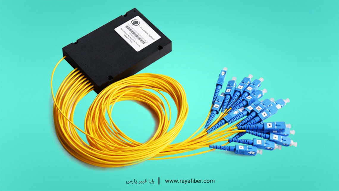
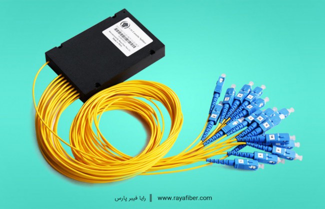
A fiber optic splitter is a passive optical device that enables a light signal on an optical fiber to be distributed among two or more fibers.
or
A fiber optic splitter is a passive optical device that can split an incident light beam into two or more light beams (or) it combines two or more light beams into a single light beam.
How fiber optic splitter works?
Whenever the light beam transmitted in a network needs to be divided into two or more light beams, fiber optic splitters are used.
When the light signal is transmitted in a single-mode fiber, the light energy cannot entirely concentrate in the fiber core. A small amount of energy will be spread through the cladding of the fiber. If two fibers are close enough to each other, the transmitting light in an optical fiber can enter into another optical fiber. Therefore, the reallocation technique of optical signal can be achieved in multiple fibers. And this is how fiber optic splitter comes into being.
Splitter does not generate power nor require power. Hence, it is a passive device. Also, splitter does not contain any electronic components. It is a simple device. Fiber optic splitter is also known as beam splitter.
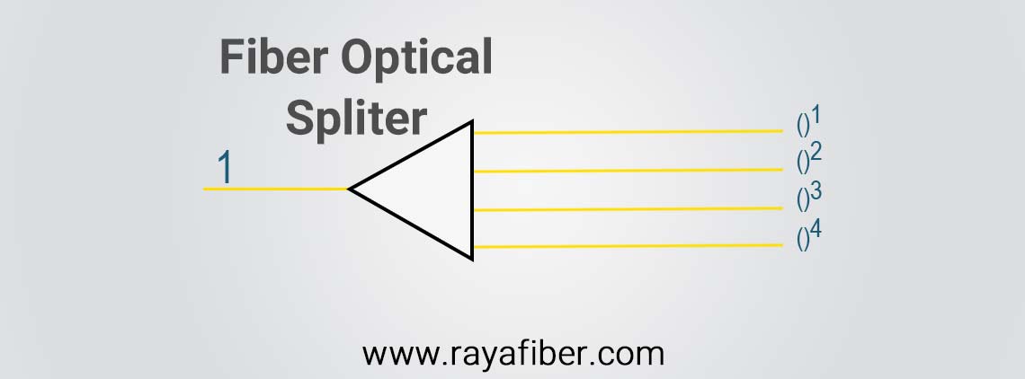
Splitters are widely used in most fiber optic networks. It has many input and output terminals, especially applicable to a passive optical network (GPON, BPON, FTTX, EPON, FTTH etc.). As a basic example, the diagram above shows how light in a single input fiber can split between four individual fibers.
The fiber optic splitters can be divided into two types: Fused Biconical Taper(FBT) splitter and Planar Lightwave Circuit (PLC) splitter.
The FBT splitters are the most commonly used splitters. FBT splitters are widely accepted and used in passive networks, especially for instances where the split configuration is smaller (1×2, 1×4, 2×2, etc.)
The PLC is an advanced technology. It offers a better solution for larger applications. In this tutorial, PLC splitter is explained.
Planar Lightwave Circuit (PLC) splitters
The PLC splitter is an advanced technology that offers a better solution for applications where larger split configurations are required. To achieve this, waveguides are fabricated using lithography onto a silica glass substrate, which allows for routing specific percentages of light. As a result, PLC splitters offer very accurate and even splits with minimal loss in an efficient package.
The PLC splitter divides the incident light beam (input light signal) into two or more light beams (output light signal) by using an optical splitter chip.
With the rapid growth of FTTx worldwide, the requirement for larger split configurations (1×32, 1×64, etc.) in these networks has also grown in order to serve mass subscribers. Due to the overall low cost and performance benefits, PLC splitters are now the ideal solutions for these types of applications.
A 1:4 Planar Lightwave Circuit (PLC) splitter is shown in the below figure. A PLC splitter is made with techniques much like those to manufacture semiconductors, and these optical splitters are very compact, efficient, and reliable.
How to determine the quality of a PLC splitter?
There are five main specifications that are outlined in this standard. The following section outlines each of the specification and their importance for a fully functional optical splitter.
1. Optical Bandpass
For a fiber optic network, there are six nominal optical bandpass ranges.
A PON system has a downstream transmission (data sent from a server to a user) using the 1490nm wavelength while the upstream transmission (data sent from a user to a server) is a 1310nm wavelength. In addition, there needs to be consideration for any requirement for RF video overlay and network testing/maintenance. RF video overlay is generally transmitted through the 1550nm wavelength.
According to the ITU L.41 recommendation, the 1550nm or 1625nm wavelength is used for network for testing and surveillance. With these considerations, the required optical band needs to be determined.
The standard operating wavelength for a PON splitter is the 1260-1650nm which covers most of the optical bands.
The optical bandpass can be tested by connecting the optical splitter to an optical spectrum analyzer with a high powered light source having a central wavelength of the required bandpass. The attenuation across the required bandpass shall meet the splitter requirements.
2. Optical insertion loss
The optical splitter is the component with the largest attenuation in a PON system. The optical insertion loss is the loss of an optical signal resulting from the insertion of a component such as connector or splice in an optical fiber system. In order to conserve the power budget of a PON system, the insertion loss from the splitter needs to be minimized.
Based on the GR-1209 standard, the maximum allowable insertion loss for an optical splitter used in a PON system can be determined by using the calculations outlined in the below table.
|
1×N Optical Splitter |
0.8 + 3.4 log2N |
|
2×N Optical Splitter |
1.0 + 3.4 log2N |
Note: ‘N’ denotes the number of output ports.
The insertion loss is tested by using a light source and power meter(or) by using an insertion loss meter.The reference power level is obtained and each of the output port of the optical splitter is measured.
3. Optical return loss
The return loss is the loss of power in the light signal returned or reflected by a discontinuity in an optical fiber or transmission line. A high return loss reduces the power reflected back to the transmitting port thus minimizing noise which may result in a system power penalty.
The return loss is tested by using a return loss meter. The input port of the splitter is connected to the return loss meter and all the output ports are connected to a non-reflective index matching gel.
4. Uniformity
Uniformity is the maximum insertion loss value between one input port and any two output ports or between two input ports and one output port. This requirement ensures that for a PON system, the transmission power at each splitter output port is the same, thus simplifying the network design.
Custom optical splitters with non-uniform coupling ratio can be manufactured for specific network deployment. In such a situation, this criteria is not applicable. The usage of a non-uniform splitter in a PON system increases the complexity in testing, design and maintenance while reducing the network flexibility.
The uniformity of the splitter can be determined by referring to the results from the insertion loss test to ensure that the difference between the highest loss and the lowest loss is within the acceptable uniformity value (≤0.5 dB).
5. Directivity
Directivity is the fraction of power transferred from one input port to another input port or from an output port to another output port. For a 2×N optical splitter, when light is injected into one of the input ports, light does not only propagate out of the output ports. Some of the light propagates back through the second input port. Similarly, when light is injected into one of the output ports, some of the light propagates back through the other output ports.
In a bidirectional transmission system such as a PON, directivity is important to reduce the power back to the transmitting port to reduce signal cross talk. In addition, a high directivity value will also cause a higher insertion loss due to the loss in optical power. So it is important to reduce the directivity as much as possible.
Directivity can be measured in a manner similar to the insertion loss test. However, the light source and power meter are connected to each of the input ports of two output ports.
Optical specifications
|
Parameter |
Value |
Unit |
|
Port configuration |
1:4 |
– |
|
Operation Wavelength |
1260-1360 / 1480-1580 |
nm |
|
Insertion Loss |
≤7.1 |
dB |
|
Uniformity |
≤0.5 |
dB |
|
PDL |
≤0.2 |
dB |
|
Return Loss |
≥55 |
dB |
|
Fiber pigtail |
ɸ0.9 |
mm |
|
Fiber connector type |
SC/APC |
– |
|
Operating Temperature |
-40 to +85 |
0C |
|
Storage Temperature |
-40 to +85 |
0C |
Advantages of PLC splitters
1. Highly accurate
2. Low cost to deploy
3. Compact design
4. High reliability
5. Efficient
6. Wide operating temperature range
7. Low insertion loss
Source: https://www.physics-and-radio-electronics.com/blog/fiber-optic-splitter/
You can rate also
Users rated:


CEO & Founder Haswell. Data lover, hobby chef, econometrician with strong experiences in the finance industry.