
Common fiber connect Problems and How to Avoid Them
February 25, 2020
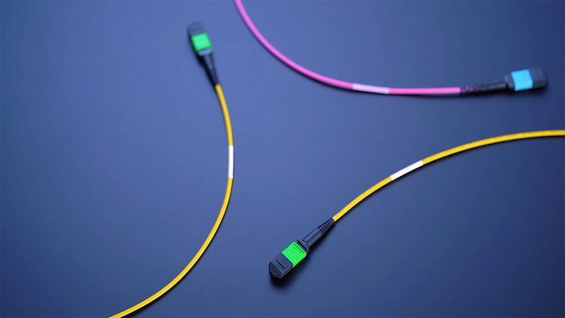
In this article we will consider the problems of optical fiber including splicing, cleaning connectors, fiber bending, fiber identification and Connector loss.
So many field problems –why?
Agenda
 • Splicing –common problems
• Cleaning and Inspecting connectors
• Avoiding Micro and Macro-bending losses
• Mismatched Connector loss
• Live fiber identification –Don’t unplug!
Bad Habits and Limited Knowledge
• I just cleave fibers with a pair of scissors –that works fine.
• No need to clean connectors –I always pull them out of the bag directly from the manufacturer and they are ready to go.
• Watch me strip off the cladding.
• I still hand polish my SM APC connectors in the field.
• My shirt cleans connectors just fine –“field clean” so to speak!
• “So, if I run over a length of cable with my chair, should I tell someone?”
Many customers bring their test equipment to class asking for help because it does not work right. We often find the connector at the source to be damaged.
Why Do Bad Habits Persist?
 • Lack of understanding about how fiber works
• Limited experience or time in the field
• OJT only allows bad habits to be passed along
• Feeling of expertise because no one has corrected you or your test results pass
• Doing things the way it ‘has always been done’ is easier than change
• Limited training for staff –often product specific, not general knowledge, process, technology training
• Training is not always followed by practice
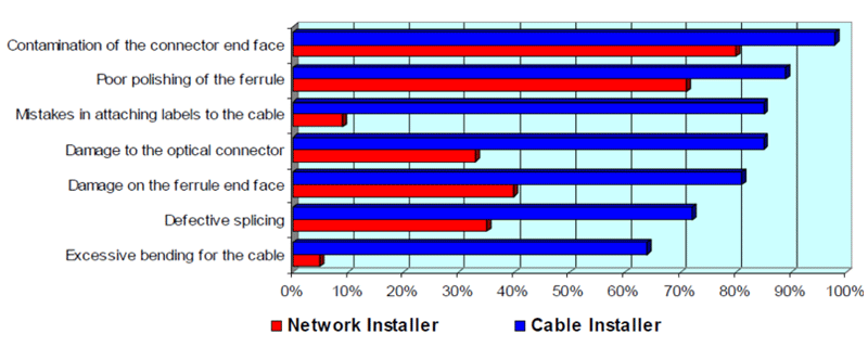
Data on the Cause of Field Problems
Cleaning and Inspection –Improvements!
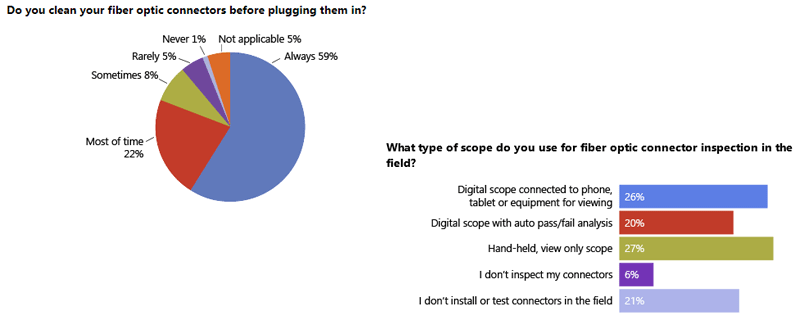
Everyone Stresses Cleaning Connectors!
Excerpts from process and best practices documents…
• CISCO: “Inspection and Cleaning are Critical –One of the most basic and important procedures for the maintenance of fiber optic systems is to clean the fiber optic equipment.”
• ARISTA: “Contaminated fiber optic connectors can often lead to degraded performance and costly, but preventable failures.”
• AT&T: “Inspect, Clean if Necessary, Inspect -One important thing to remember in handling fiber optic connectors is that the fiber end face and ferrule must be absolutely clean before connections are made.”
•JUNIPER NETWORKS: “Note: Improper cleaning can result in high attenuation due to dirt or dust, or can cause mechanical damage to the fiber end face, resulting in decreased performance.”
“Defective Splicing”
• Poor cleaving and splicing practices:
– Cause excess loss (misalignment, air bubble, poor cleave)
– May cause excess reflection (air bubble or air gap at poor cleave or break)
– Poor cleaves create rework and add time to a splice job
• Prevention:
– Clean V-grooves, maintain splicer electrodes, use correct splicer settings
– Strip and thoroughly clean fiber beforecleaving & splicing
– Use a good cleaver and maintain it! Do not clean fiber after cleaving.
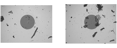
A Good Splice Requires a Good Cleave
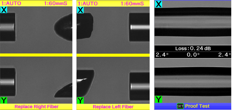
Left:Scissor cleave Right: Stripping tool cleave
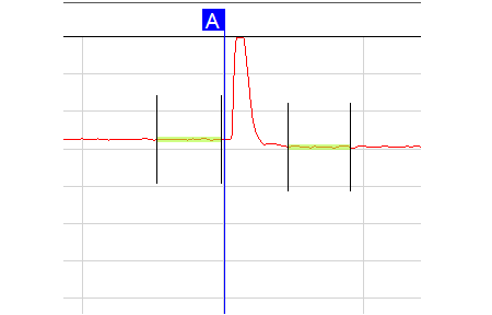
Clean Connectors Matter!
|
|
|
Dirty connectors = high insertion loss and high reflectance
|
|
|
|
|
|
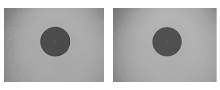
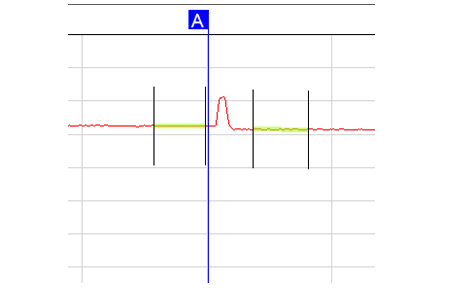
Clean connectors =low insertion loss and low reflectance
|
|
|
Detecting Dirty or Damaged Connectors
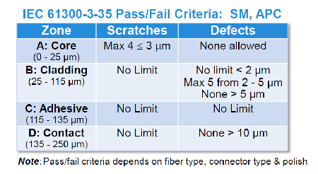
Inspect with Video Microscope & Evaluate to IEC-61300-3-35
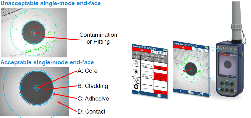
IEC Inspection Criteria Example
Connector Cleaning
Clean bothconnectors before mating!
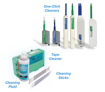 One-Click Cleaners (dry cleaning)
• Easy, fast & effective; Low cost per clean
• Cleans jumper connector ends
• Cleans through patch panels
Solution & Wipes (wet cleaning)
• Effective on stubborn contamination
• Use solution which leaves no residue
• Wipes or absorbent sticks to dry
• Use sticks to clean through bulkheads
Replacing Damaged Connectors
• Field-installable, factory-polished mech. splice connector
– Index matching gel & high quality cleave
– Few tools needed, fast assembly
– Visual connection verification with VFL
– Available for single-mode & multimode
– 900μm standard; 2 and 3mm boot kits available
• Field-installable, factory-polished fuse-on connector
– Fusion splice connector; Eliminates splice trays
– Performance less dependent on technician skill
– Splicer required
– No index matching gel, crimping, polishing or epoxy
– Available for both single-mode & multimode
– 2 and 3 mm cordage available
Poor Practices Can Lead to Added Loss
- Macrobending
- Microbending
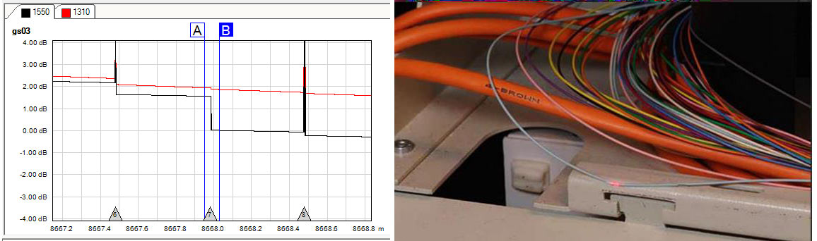
Macro-bend Detection
• Test network using OTDR at short (1310 nm) and long (1550 or 1650 nm) λs
– Distinguish macro-bends from poor splices by higher loss at longer λ
– For long-haul networks, detect macro-bends by testing at 1550 & 1650 nm
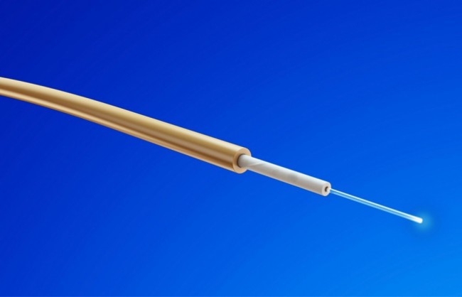
– Use VFL (visible red laser) to pinpoint bends in closures & cabinets
Eliminating Losses Due to Bends
 • Remove any detected tight bends found during testing
• Ensure fibers not pinched when closing splice closure or sliding in splice trays
• Be sure cable ties are not too tightly cinched
• Looks for fiber pulled tightly over the edge of a panel/tray
• Don’t hang large coils of cable/fiber over an edge
• Test with an OTDR and/or VFLto verify bends have been resolved
Avoid Mating Mismatched Connectors
• FTTH networks usually built with angle-polished (APC) connectors
– Minimizes connector reflections –a source of noise in 1550 nm RF networks
– Ensures unused (open) PONsplitter ports won’t create strong reflections
• CAUTION: Do not mate UPCconnectors to APC connectors!
– Mated UPC - APC results in excess reflection and loss
– Poor OTDR results will be obtained when mismatched connectors mated
– Use SC-UPCto SC-APC hybrid jumpers or launch cables as necessary to connect test equipment with UPC to APC
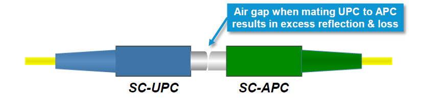
• Connecting PC to APC connectors = high loss & excess reflection

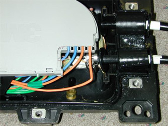
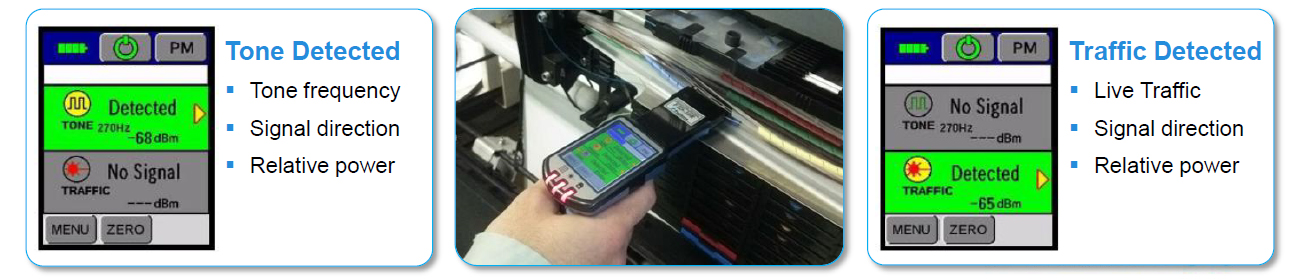
Live Fiber Identification
Prevent outages –Check for Live Fiber beforedisconnecting!
• Optical Fiber Identifiers (OFI) clamp-on to detect light in fiber
– Do not require disconnecting fiber to test
– Works on 250μm bare fiber, 900μm buffered, 2 & 3 mm jacketed fiber
– Detects & reports Traffic or Tone and direction
– Use Tone (270, 330, 1k, 2k Hz) for positive ID of specific out-of-service fiber
• Look for an OFI that works on bend-insensitive fiber!
Avoiding Common Field Errors -Summary
• Train staff on proper procedures and WHY they are important.
• Clean and Inspect fiber optic connectors before mating –every time!
• Use the right materials to clean your connectors.
• Properly clean & cleave fibers & follow process steps for good splicing results.
• Use care when managing fiber in closures, trays, cabinets –avoid sharp bends and pinch points.
• Be aware of connector types –Avoid connecting UPC to APC.
• Get the right tools for troubleshooting live links –Fiber Identifiers are useful but should work with BI fiber.
Source: www.aflglobal.com
You can rate also
rate4.5from2people


CEO & Founder Haswell. Data lover, hobby chef, econometrician with strong experiences in the finance industry.