

Fiber Optic Fundamentals
November 24, 2019
The world we live in today is based on the rapid transfer of huge data. Not long ago, data was transmitted from one device to another using copper cables. In recent years optical fibers have replaced copper cables and have become the most important means of data transmission due to their very high bandwidth.In this article, we will review the basics of fiber optics.
Fiber Optic Basics
1-Refraction and Total Internal Reflection
Refraction occurs when light passes from one homogeneous isotropic medium
to another; the light ray will be bent at the interface between the two media.
The mathematical expression that describes the refraction phenomena is
known as Snell’s law,
n0 sinΦ0 = n1 sinΦ1
where
n0 = the index of refraction of the medium in which the light is initially
travelling,
n1 = the index of refraction of the second medium,
Φ0 = the angle between the incident ray and the normal to the interface, and
Φ1 = The angle between the refracted ray and the normal to the interface.
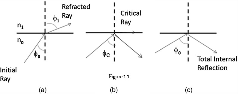
Figure.1 Ray incident at a plane interface between a low- and high-index medium.
Figure 1(a) shows the case of light passing from a high-index medium to a lower-index medium. Even though refraction is occurring, a certain portion of the incident ray is reflected. If the incident ray hits the boundary at everincreasing angles, a value of Φ0 = Φc will be reached, at which no refraction will occur. The angle Φc is called the critical angle. The refracted ray of light propagates along the interface, not penetrating into the lower-index medium as shown in part Fig.1(b). At that point, sin Φc equals unity. For angles Φ0 greater than Φc, the ray is entirely reflected at the interface, and no refraction takes place [see Fig.1(c)]. This phenomenon is known as total internal reflection.
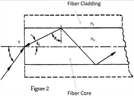
Figure.2 Ray passage along a flat-ended optical fiber.
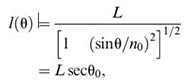
In Fig. 2, a ray of light incident upon the end of the fiber at an angle Θ will be refracted as it passes into the core. If the ray travels through the highindex medium at an angle greater than Φc , it will reflect off of the cylinder wall, will have multiple reflections, and will emerge at the other end of the optical fiber. For a circular fiber, considering only meridional rays, the entrance and exit angles are equal.
Considering Snell’s law for the optical fiber, core index n0, cladding index n1, and the surrounding media index n,
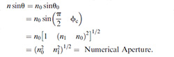
The quantity sinΘ is defined as the numerical aperture (NA). (For Φ0 = Φc, Φ1 = 90 deg; therefore, sinc = n1/n0.) The NA is determined by the difference between the refractive index of the core and that of the cladding. It is a measure of the light-acceptance capability of the optical fiber. As the NA increases, so does the ability of the fiber to couple light into the fiber, as shown in Fig. 3(a). The larger NA allows the fiber to couple in light from more severe grazing angles thereby increasing the acceptance angle and the acceptance cone of light entering the fiber. Coupling efficiency also increases as the fiber diameter increases, since the large fiber can capture more light [see Fig.3(b)]. Therefore, the maximum light-collection efficiency occurs for large-diameter-core fibers and large-NA fibers.
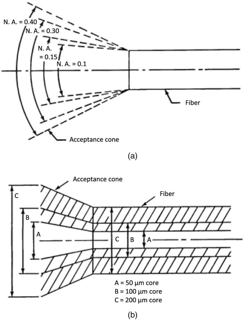
Figure.3 Acceptance angle associated with (a) numerical aperture and (b) core size.
2-Meridional Rays
The definitions of total internal reflection and numerical aperture have been based on meridional ray analysis (i.e., the ray path, through its numerous reflections, as it passes through the longitudinal axis of the fiber). Using Fig. 2 as a reference, it can be shown that the length of a meridional ray in a fiber in air (n = 1) is
where L(Θ) is the length of the optical path for a ray inclined to the fiber axis at an angle Θ0, and L is the length of the fiber measured along the fiber axis. It is interesting to note that the length of the optical path for an incident ray depends only on the fiber length, the angle of incidence, and the refractive index of the fiber core, while being independent of the fiber diameter. The number of reflections, however, is dependent on fiber diameter. The larger the diameter of the fiber, the fewer the number of reflections,
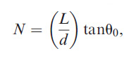
where N is the number of reflections at the core–cladding interface, and d is the fiber diameter.
3-Skew Rays
In general, meridional rays describe very simplified ray propagation. Often rays are skewed in nature and dominate the optical properties of the fiber. These rays affect the “real” ray propagation and alter the simplified definition of numerical aperture, ray path length, and number of reflections.
Skew rays travel along a helical path
4-Bent Fibers
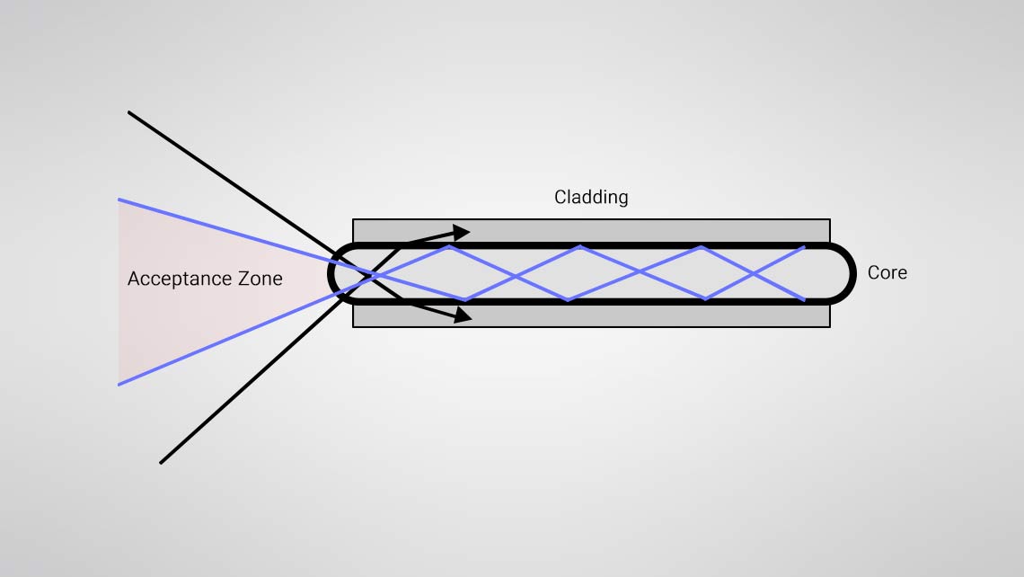
The angle between the light ray and the normal to the plane of reflection is defined by the angle Φ. However, as shown in Fig. 5, when the fiber is bent, the plane of reflection and the reflective ray rotate by the angle δ. Therefore, for a curved fiber, the angle between the reflected ray and the tangent at the reflection point is Φδ. In a straight fiber, for Φ > Φc, the rays will be totally internally reflected. In a bent fiber, the effective critical angle is reduced by δ. Therefore, rays incident between Φc and Φc δ will be lost through the cladding of the fiber. The effective critical angle is reduced in a bent fiber, as is the amount of light that can be injected into the fiber.
Figure.5 Bending effects on a critical angle.
Figure 6 illustrates a curved fiber with rays traced through several internal reflections. The multiple reflections in a bent fiber with a constant radius of curvature do not increase the bending loss since the steepness of the rays as they hit the sidewalls of the fiber does not increase (i.e., Φ1 = Φ2 = Φ3 ). The bending loss occurs primarily at the transition from the straight to the bent section (a change in one curvature to another curvature for multiple bending points).
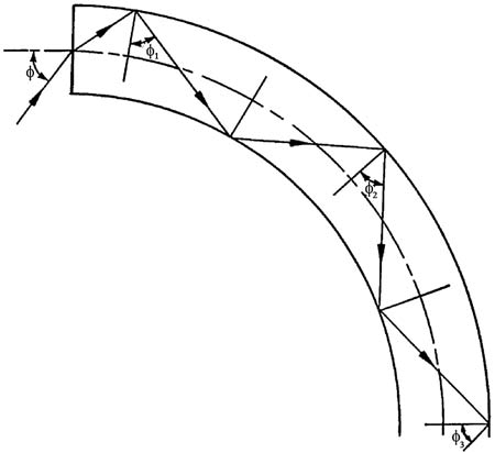
Figure.6 Multiple reflections in a bent fiber.
5-Mechanisms of Attenuation
Attenuation or loss is defined by the following equation:
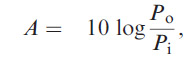
where A is the attenuation, and Pi and Po are the input power and output power, respectively. The negative sign arises from the convention that attenuation is negative. Attenuation is measured in decibels (dB) per unit length, typically dB/km. Loss can vary from 1 to 1000 dB/km in useful fibers with the various causes of loss often being wavelength dependent. The causes for loss are absorption, scattering, microbending, and end loss due to reflection, as shown in Fig. 7.
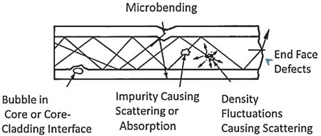
Figure.7 Causes for attenuation in an optical fiber.
Fibers for telecommunication applications use wavelengths in the C band, centered around 1550 nm. The loss decreases at higher wavelengths because inherent Rayleigh scattering losses are decreased, since the scattering is proportioned to 1/ λ4, where λ is the wavelength.
6-Evanescent Wave
Energy is carried in the cladding as well as the core of the fiber. This is referred to as the evanescent wave phenomena. There is an exponential loss of energy in the fiber cladding as the distance from the fiber core is increased. Fig.8 shows a wave incident on the core–cladding interface. The wavefronts (planes of constant phase) are shown as dotted lines. The arrows represent the wave normals. The direction of the arrows indicates the flow of energy. The superposition of incident and reflected beams results in a wave where the wavefront is perpendicular to the interface. The energy distribution in the core has its maximum near the interface. The energy in the cladding falls off exponentially.
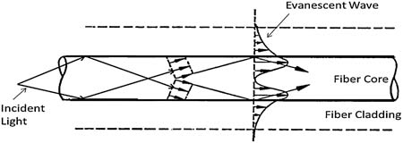
Figure.8 Evanescent wave phenomenon.
7-Cross Coupling
Cross coupling involves the transfer of light from one adjacent fiber to another. The extent of coupling between two adjacent fibers in close proximity is a function of the following: the diameter of the fibers; the spacing between the fibers; the length in which the fibers are in close proximity; the index of the fiber core, the cladding and the index of surrounding media; the thickness of the cladding; the wavelength of light in the fiber; and the particular modes excited in the fiber.
Clearly, a precise mathematical expression for the phenomenon is quite complex. By properly selecting the various parameters, it is possible to completely transfer all of the energy in one fiber to an adjacent fiber. The length required for the transfer is referred to as the beatlength. For large fiber diameters, the energy transfer is limited over some length; a state of equilibrium will be reached. It has been found that as the wavelength increases, the beatlength decreases. As a result, the relative intensity of energy in adjacent coupling fibers will vary with wavelength.
8-Fiber Types
The multimode and single-mode fibers have similar refractive-index profiles, but the single-mode fiber has a much smaller core. The single-mode fiber has much less dispersion and a sharp output pulse. The graded-index fiber has an intermediate output pulse. The multimode fibers are used to increase bandwidth (i.e., information-carrying capacity) as compared to multimode fibers. Step-index fibers have an index of refraction that is constant in the core and the cladding and stepped at the core–cladding interface. Table.1 lists some of the fiber types and their various properties. A comparison of a single-mode and multimode fiber is illustrated in Fig.9.
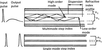
Table 1.1 Typical properties of various fiber types
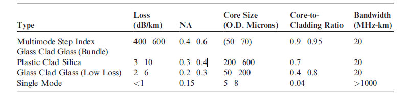
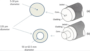
Figure 10 Comparison between (a) single-mode and (b) multimode optical fibers.
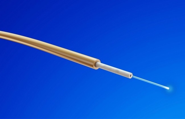
As optical fiber technology has advanced, a broad range of fibers have been developed to increase performance, especially for extreme environments. Ultralow-loss fiber with minimized water peak absorption is commercially available, as well as fiber that is insensitive to microbending. In addition to the fiber composition and structure, advanced coatings have enabled optical fiber to be functional in extremely harsh environments. Figure.11 is a very basic fiber optic cable. It consists of a buffer layer over the fiber, a strength member, and an outer jacket. As the environmental requirements become more severe, the cable construction becomes more complex
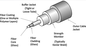
Figure 11 Basic elements of a fiber optic cable.15
Source: Fiber optic sensors : fundamentals and applications / D.A. Krohn. Fourth edition.
You can rate also
rate4.67from3people


CEO & Founder Haswell. Data lover, hobby chef, econometrician with strong experiences in the finance industry.